ILA Evo: Meta’s journey to reimagine fiber optic in-line amplifier sites
Today’s rapidly evolving landscape of use cases that demand highly performant and efficient network infrastructure is placing new emphasis on how in-line amplifiers (ILAs) are designed and deployed. Meta’s ILA Evo effort seeks to reimagine how an ILA site could be deployed to improve speed and cost while making a step function improvement in power [...] Read More... The post ILA Evo: Meta’s journey to reimagine fiber optic in-line amplifier sites appeared first on Engineering at Meta.

- Today’s rapidly evolving landscape of use cases that demand highly performant and efficient network infrastructure is placing new emphasis on how in-line amplifiers (ILAs) are designed and deployed.
- Meta’s ILA Evo effort seeks to reimagine how an ILA site could be deployed to improve speed and cost while making a step function improvement in power efficiency.
Over the past year, Meta has been on a journey to reimagine fiber optic in-line amplifier (ILA) sites. An important piece of network infrastructure, ILAs serve to amplify optical signals and are often placed in remote locations between data centers. If one ILA fails, an entire intercity route fails, and if one ILA cannot grow, the entire fiber route is constrained. Meta is excited to introduce new ideas and concepts to help modernize the ILAs for tomorrow.
To that end, we’ve launched the ILA Evo effort to overcome the historic design constraints of today’s ILAs, namely:
- The minimal skilled labor and raw material required at the deployment site;
- The requirement that buildings meet local snow, wind, and seismic load along with fire codes and health and safety regulation – plus lifespan greater than 25 years;
This new effort seeks to propel advancement through several new requirements:
- Requiring the building and inside plant (ISP) must be deployed in three to four days.
- Reducing the need for specialized heavy equipment (avoiding the cost and time for heavy-lift cranes to travel to a remote site).
- Minimizing concrete (avoid cost and time to transport, form, tie rebar, pour, and cure concrete).
- Reducing the power usage effectiveness (PUE) to less than 1.5 – nowhere near Meta’s operational data center PUE average of 1.09 (2023 average), but an achievable and significant improvement.
A short history of ILAs
Fiber optic cable networks have seen exponential growth in both size and capacity since GTE launched the first fiber optic network in 1977. U.S. network operators would install 20,039 mi (32,250 km) of intercity fiber routes by 1985. This would quadruple to 83,618 mi (134,570 km) by 1989 and double again to 159,779 mi (257,149 km) by 1998, with MCI, Sprint, USTelecom, and WilTel being the major players in those early days.
As fiber was rolled out along roads, railways, and pipelines, real estate to house optical signal repeaters was developed in parallel. What later became known ILA sites were spaced 18 to 25 miles (30 to 40 km) apart. With rapid improvements in both optical fiber purity and composition, plus advancements in optronics, spacing soon doubled into the 50 to 60 mile (80 to 100 km) range where it has largely remained until today.
Early ILA building designs were roughly modeled on Bell Telephone central offices, albeit a shrunken down version: concrete shells (or stick framed construction on a steel I-beam base) placed atop concrete foundations; wall-mounted HVAC units; -48V power distribution; lead-acid batteries; diesel backup generators and so forth surrounded by chain link fences.
Buildings were constructed in a central location with ISP fitted into the shell before shipment to the site (via specialized motor carrier) and placed with a heavy-load crane. However, unlike the remarkable (and ongoing) advancements in fiber and optronics (e.g., CWDM to DWDM to Coherent DWDM), ILA sites themselves have received little attention.
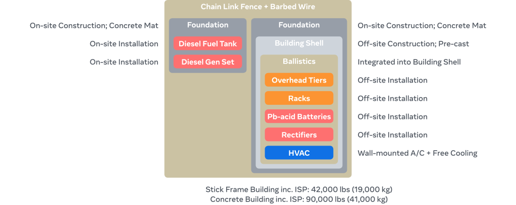
Today’s ILA buildings are often larger, with more efficient HVAC systems. Components like security and building access systems have been modernized, but if you dropped a field technician from 1990 into one of today’s ILAs, they’d have little difficulty navigating. Historically, ILA sites haven’t required significant evolution, however newfound capacity growth and innovation has warranted the development of new ILA approaches.
The structure of ILA Evo
Working with global engineering consultancy AECOM, we’ve organized the problem and our engineering efforts into several categories: different building systems and foundations; a new ISP installation method; alternative ballistics protection; introducing more efficient cooling; and modernizing backup power systems.
Building system
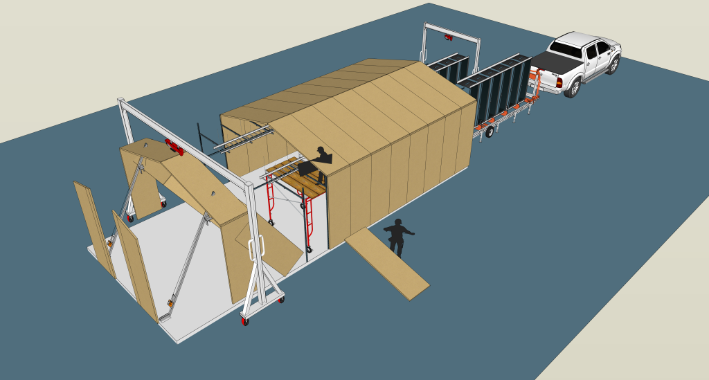
Identify lightweight building designs which can be flat packed for easy, quick shipment and unloaded at the deployment site using a lift gate. Our emphasis has been on buildings composed of fiberglass-reinforced polymer (FRP) aka glass-reinforced polymer (GRP) wall and roof panels light enough for two people to handle, but sturdy enough to meet our design needs. There is a robust ecosystem of companies offering solutions in this space. This approach also allows for slightly taller buildings than prefab to provide additional overhead space for HVAC system elements or other components.
Building foundations
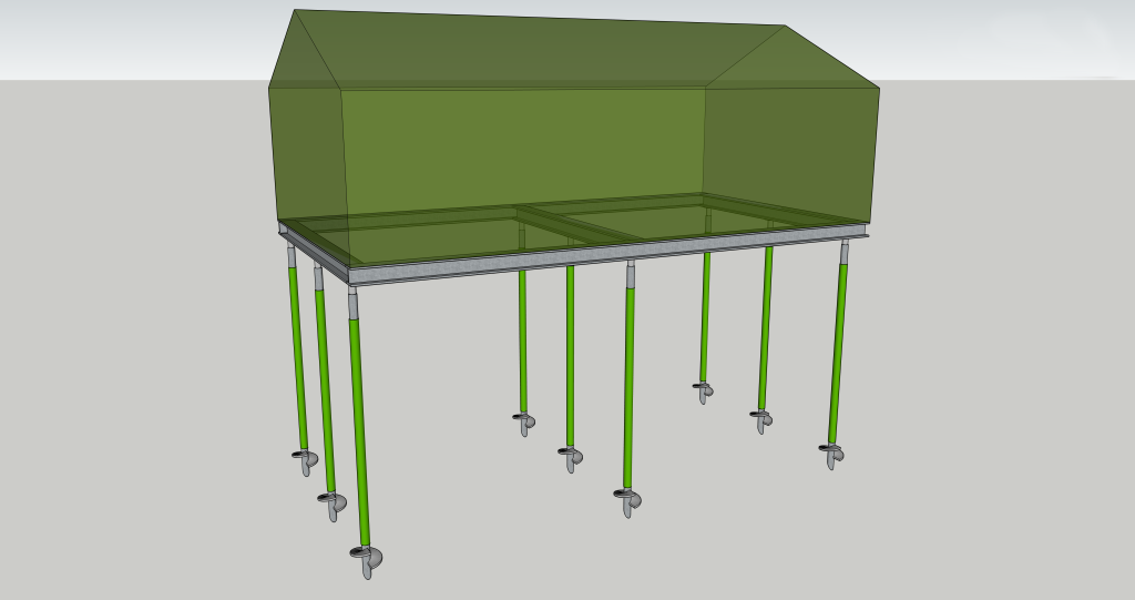
Where geology permits, utilize low- or no-concrete foundation designs for easier deployment into both greenfield and brownfield sites. Typically, ILA buildings sit atop slab-on-grade foundations with a perimeter edge return. This design works well in a variety of soil conditions and is well suited to the weights involved. However, as we pursue lighter buildings, other foundation designs become possible. In particular, the project has focused on steel or FRP I-beams over concrete pad footings or helical steel screw piles. Both options offer the potential for both lower cost and more rapid deployment.
Manufactured owner-furnished equipment ISP
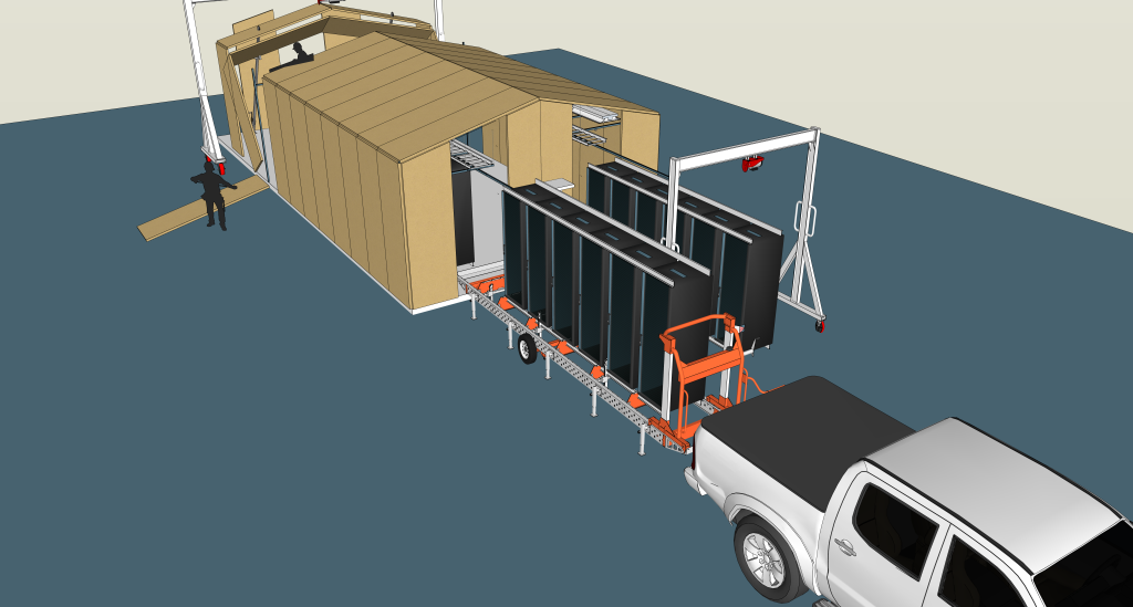
Devise a process for rapidly installing ISP to minimize post-construction interior dust and debris clean-up. We envision employing a manufactured owner-furnished equipment (MOFE) process for ISP: six rack modules consisting of equipment racks and overhead tiers supported by an exoskeleton, and movable on casters, are preassembled in a centralized, clean factory-like environment. Like the building system, these can be delivered on regular trucks with lift gates and modules rolled into the building to be bolted down.
Ballistics
Where required, provide appropriate ballistics protection; e.g., NIJ 0101.06 Level IIA. However, we felt assigning this function to the building system wasn’t the only option, so we’ve left open the possibility of ballistic privacy fences and other ideas as ways to solve this requirement which offers more flexibility for what “inside the fence” could look like.
Cooling
The single biggest opportunity to improve PUE lies in introducing more efficient cooling tech combined with higher temperature set points. PUE hasn’t historically been a focus metric for small telecoms sites, but this needs to change. Traditional sites use self-contained, wall-mounted HVAC units that rely on large fans to force air through the building without a duct system. This approach works, but is not very efficient: North American ILA PUE is typically between 2.5 and 3.0. However, over the past few years, power requirements have moved from 600-800W per rack into the 2-4 kW range. With increasing power density, we began looking for other options which could do the job more effectively and efficiently (i.e., reduce PUE).
Main elements:
- Radically improve ILA site HVAC efficiency with advanced passive (i.e., compressorless) and/or liquid-based cooling tech.
- Because ILAs are unmanned, allow the building to run hotter: e.g., increase temperature set points from typical 22°C (72°F) to >35°C (95°F); most optical transport kit is GR-63-CORE NEBS-3 compliant and able to run continuously at 40°C (104°F).
- Thermally “leaky” building systems; i.e., not air leaks , but lower R-value walls.
- Move rectifiers and batteries into outdoor cabinets: more space for optical gear and less heat generation.
- Utilize cool surface materials and coatings (e.g., heat reflective paints) to further reduce solar heat load.
The project investigated many hyper efficient options such as chilled beams (ceiling mounted, air-to-liquid heat exchangers) combined with a ground-based heat exchange (water or glycol circulating in a closed, buried ground loop), but unfortunately, none could handle 24 x 2 kW. However, a loop thermosyphon system coupled with a high-efficiency compressor (a helper used during the hottest part of the hottest days) could achieve our PUE <1.5 goal. Similarly, scaled-down chiller and computer room air conditioning (CRAC) units supplying liquid cooling into a thoughtfully designed floor plan could get us to that same goal.
The project hasn’t made a final selection yet as these technologies will make our goal of “no cranes” difficult to achieve, but we believe we have line-of-sight to a solution.
Backup Power
Investigate modern alternatives to diesel generators and lead-acid batteries for standby power. We are considering substitutions for diesel generator backup that may include H2 fuel cells, capacitors, or other solutions based on location and commercial feasibility.
Additionally, we have investigated a range of battery technologies. At the moment, the economics aren’t attractive for this scale. In the meantime, we believe an H2 fuel cell combined with a small NaNiCl molten salt battery system (to handle site load for a few minutes while the fuel cell spins up and takes load) is an attractive, low maintenance solution.

Macro benefits of ILA Evo
Beyond the technical aspects, ILA Evo brings potentially powerful commercial and risk management benefits: supply chain and ability to stockpile.
Starting with the familiar current ILA supply chain, the chief advantage is completing the majority of work at a single site. However, this creates challenges in terms of cost, the complexity of scaling production up or down, and the difficulty and cost of transporting the necessary heavy equipment to remote sites. Additionally, the feasibility of stockpiling current ILA buildings is debatable: The space requirement would consume valuable real estate at the production site and staging them off-site simply amplifies the transportation issue to move them multiple times.
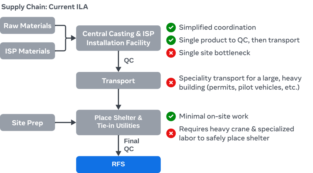
Looking to ILA Evo and starting with a new disaggregated supply chain, many ISP materials and other items like HVAC units would most likely come from the usual sources, but these sources already tend to be scaled. Other elements such as the building system and MOFE ISP would be manufactured or assembled by companies that are not necessarily part of today’s telecom ecosystem.
Additionally, the process is very different. Concrete and stick framed buildings are created via a construction process, the nature of which is bespoke and relatively low volume. ILA Evo is predominantly manufacturing or assembly processes, which are inherently geared toward scale, including the possibility of 24×7 operations.
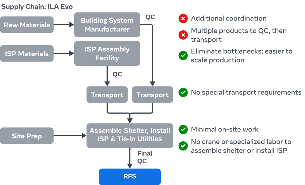
Next, stockpiling. It’s not hard to imagine manufacturing 500 building systems, packed efficiently and ready for next day shipment. One can also imagine 2,000 MOFE ISP modules (four for each 24 rack building) preassembled and ready to ship. Additionally, purchasing in bulk allows vendors to de-risk their own investments and achieve scales required for cost compression not possible with today’s designs.
Crossover with current ILA design
One final consideration is identifying ideas that could be retrofitted into existing sites. Putting aside a different building system and MOFE ISP, the HVAC system and the other “efficiency tweaks” could go into existing sites. Similarly, H2 fuel cell backup power could be applied. We also expect to explore substituting commodity ISP materials for their FRP analogs. If this works, FRP equipment racks and ladder racks (which have a lower carbon footprint than steel or aluminum) could also be an option for existing sites.
What’s next?
Following the completion of our research and design phase, there are a number of next steps planned for 2025:
- The project has already engaged fiber optic operators in North America and Europe to gather early feedback and gain their insights. In the coming months, we expect to expand this consultation with operators in Latin America, Africa, Middle East, and Asia.
- A prototype site showcasing some of the best ideas from this work.
- We plan to create and broadly share blueprints, bills of material, and analyses that show our path and help seed operators’ own research, engineering, and technical real estate product development.
The post ILA Evo: Meta’s journey to reimagine fiber optic in-line amplifier sites appeared first on Engineering at Meta.


/cdn.vox-cdn.com/uploads/chorus_asset/file/21694346/acastro_200803_1777_tikTok_0001.0.jpg)


